Click on any of the photographs to enlarge!
It is the last few days before Christmas and the last of the preparations are being hurriedly thought about, by me, and carried out by Sue. Cakes are being cooked and the Christmas tree is making the place feel like Christmas. At this time of the year Meccano thoughts are on the Christmas Challenge that has become a regular feature in the Spanner II list. It usually causes a lot of debate and can take weeks for the rules to be clarified. It seems to be a bit of a tradition. This year, I took the bull by the horns and jumped in to proposed a Christmas Challenge much earlier than is the norm, expecting nothing more than for it to take an age to get under way.
 |
| Sue's Christmas fireplace |
To my surprise it all fell into place and we were off. The simple rules of the competition can be found
HERE, if you would like to take a look. Models are exported into the
NZ Meccano Gallery where Bob T. does a splendid job of sorting out all the pictures and displaying them next to the manual model they are based on. There is also a voting system to establish viewer's favourite model. No prizes are given but the top place is where everyone aspires to be, come the 31st December. I usually end up in the middle of the list, if I actually get around to entering. We will not talk about the year Sue came third with her Santa's Fireplace complete with Christmas stockings hanging up. My Derrick came fifty-third.

One of the first people to enter the competition this year was Douglas Laing from Johannesburg. Douglas had submitted a VirtualMEC drawing of a Hammer Head crane. Unfortunately I found myself in the unenviable position of having to disqualify it for not complying with the rules. Christmas challenge aside, the model was very appealing and I decided to have a go at building it. Luckily my disqualification of his entry was taken with good grace and we started corresponding regarding the build. Douglas sent me his VirtualMEC model file and it was then that the wheels started to come off of this plan. The original 'still' from the drawing is shown on the right. VirtualMEC has its limitations and one of them is that nobody taught it how part no. 40 works. For those without an encyclopaedic knowledge of meccano parts numbers, that is a Hank of Cord - String to you and me!
It is very easy to draw parts in impossible positions without realising it. The trading of e-mails between London and Johannesburg began and progress was made slowly. The other thing to come out of this was the realisation that the VirtualMEC program had no 'gravity' and what would stand up in the virtual world would not necessarily do so in reality.
The Build
I started with the tower as that looked simple enough. And it is if you have all the parts. Closer inspection reveals the bracing is actually 5½ inch narrow strips. Who has twenty-four of those laying about? Even we don't have that sort of quantity to hand. These parts were not included in the sets and were only available as spare parts, which were hard to come by even when Meccano were selling spares. In fact they are so thin on the ground around here I know exactly how many we have and exactly where they all are. There are thirty-four of them built up in Sue's replica Ferris wheel dealer display model and just two more sitting in the drawer.
 |
The top of the tower showing the
overlapping 3 inch narrow strips
joined behind the washer |
Can you believe it, we are overrun with most parts in this house (so much so we are selling off our surplus at
RalphsShop.com) and the first thing I look at is one of the very few parts we are short of. Luckily there is an easy work-around. The point at which the bracing crosses is detailed with a large washer. This means the 5½ inch strips can be replaced with two 3 inch strips overlapped by one hole and secured with the bolt that is used to fit the large washer. It was at this stage when it dawned on me that the top and bottom of the tower is finished off with 4½ inch girders. Another part that is not that common and Sue had just used at least eight of them in her latest model. A rummage around in our 'back-stock' turned up a further eight to allow me to complete the tower. So far, so good but next it was time to build the boom. Looked like a piece of cake - yeah right!
Building the outer framework was fiddly, with all those double girders, but once it was sorted out that was the easy bit. Now the fun began. Try as I might I could not get several of the narrow strips used to brace the side frames to fit anywhere near where the drawing indicated they should be. It was at this point that Douglas sent me the drawing file. Inspection of this revealed that several of the strips were indeed not aligned with the holes at all and just hidden behind the frame. In all cases the ends of the strips can be trapped between the sections of the frame. Surprisingly, this worked well and the resultant construction is perfectly rigid enough.
 |
| View from above better sows the construction |
It was at this point the 'Gravity' issue became obvious. This thing was very front heavy and was going to require a good deal of weight in the back end to keep it standing upright. Not wanting to add a huge block to the back of the boom I adopted a 'thick-floor' policy and added the best part of half a kilogram of 4½ inch strips to form a floor. In case you are wondering, that is 65 strips in 5 stacks of 13! Even that was not enough and a few 3½ inch strips were added to the inside of the back of the winding house.
 |
| Inside the winding house with the roof removed |
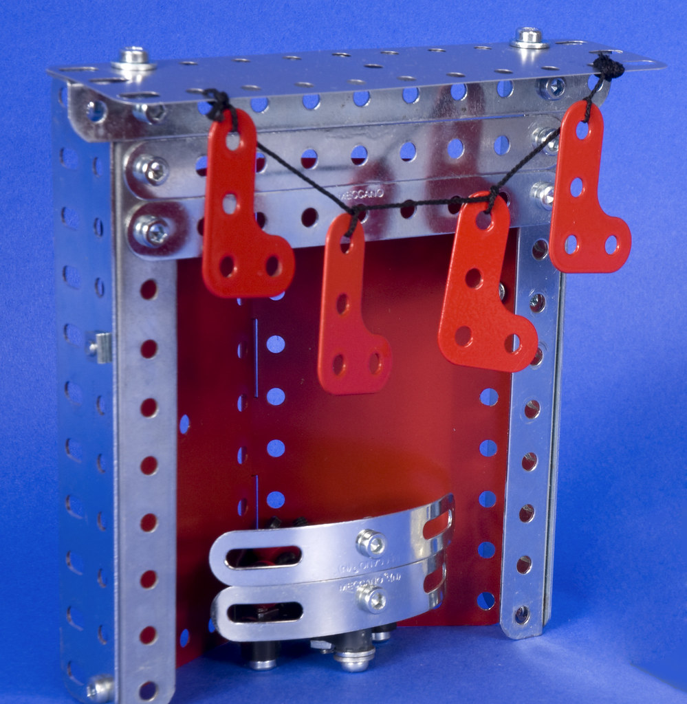
It is nice to keep a model simple, in this case the simplicity was maintained by keeping the hand operation and not getting carried away with a bucket load of gears and brassware. However, a few improvements can make the operation easier. Guide pulleys will stop the cord chafing and aid smooth operation. The most obvious addition is the winding drum for the hoist. This is made by forcing a couple of Chimney Adaptors into either end of a Sleeve Piece and trapping it between a couple if the small diameter bush wheels. The cord used is Ralph's String, fine. It is available in cut lengths
HERE. It is anchored by passing it through one of the holes and out via the expansion slot in the sleeve piece. A double knot tied in the end of the cord will stop it passing through the slot. making a neat means of securing it. A spring forces a ½ conch diameter Bossed Pulley fitted wit an 'Aircraft Tyre' against the inside of the Flat Plate to form a brake for the hoisting cable. Pushing the winding wheel in, against the spring, allows the drum to be wound easily and releasing the wheel will brake the drum, holding the load in place.
 |
| The tyre is acting as a brake, held against the plate by the spring seen in the picture above |
Getting the tension right in the crab travel lines is crucial and is helped with the addition of a tension spring incorporated in the crab. The cord is tied to one end of the spring and then it is fed through the front bracket, around a pulley at the front of the boom and back through the crab to the winding house and under the guide pulley. There it is wound around a rod before being passed over the pulley guide this time and tied to the other end spring, under tension.
 |
| The crab incorporated a tension spring |
The hoisting cord passes under the lower guide pulley an out of the winding house to the crab. it then passed over the first 1 inch free-running pulley down to the block and back up again before being secured to the front of the boom ensuring the load will stay level no matter what the position of the crab along the boom.

The hook block in the original plan uses flat trunnions in the usual configuration to make the block. However in this scale I felt it looked a little too bib so I made a slightly lighter one using a pair of brass ½ inch Pulleys without boss held between a pair of 1 inch corner brackets. A vintage red part no. 57c Hook is held between a pair of red 1 inch narrow strips. Short pivot bolts and thin brass M4 washers were used to hold the corner brackets together and space the pulleys away from the bracket to prevent them binding. Hexagonal nuts were locked together to hold everything in place, but still leaving the pulleys free to rotate. The small size of these nuts is not a great deal different from the size of the socket head bolts an therefore look better than any other solution available, such as Meccano locking nuts. A shorter 3/8 inch Long Bolt is used to suspend the hook.After assembly it was obvious that the paint in the holes of the painted parts were causing it all to bind in use. A bit on manual working in by working the pivot points by hand soon loosened it up and a few drops of oil on the pivot bolts and hook suspension gear worked wonders.
 |
| The finished winding hose with roof |
Collars were added to the ends of the guide pulley rods and a couple of 4½ x 2½ inch Flexible Plates were pre-formed on the bending machine before being secured in place to complete the winding house.
I am please with the way it turned out and it just goes to show how Meccano manual models can models can be inspirational and lead to something completely different as the idea is passed on and evolved. Douglas said he made his drawing in an attempt to improve an old manual. Model 4.1 HAMMERHEAD CRANE from the 1951 no. 4 set.
Although Model 4.13 firm the 1962 Manual looks to be more like an ancestor of the model in his original drawing.
Either way, as he says in his original post on the Spanner II list, it can't have wheels and be called a Hammerhead crane.
Okay, that has got the crane building bug satisfied for another little while I am off to look at making an entry of my own to the Christmas Challenge over on the Spanner II list. If you are not familiar with Spanner II and want to know more, click
HERE or follow the link in the light-blue Spanner II information box in the left hand column of this page.
Ralph

 One of the first people to enter the competition this year was Douglas Laing from Johannesburg. Douglas had submitted a VirtualMEC drawing of a Hammer Head crane. Unfortunately I found myself in the unenviable position of having to disqualify it for not complying with the rules. Christmas challenge aside, the model was very appealing and I decided to have a go at building it. Luckily my disqualification of his entry was taken with good grace and we started corresponding regarding the build. Douglas sent me his VirtualMEC model file and it was then that the wheels started to come off of this plan. The original 'still' from the drawing is shown on the right. VirtualMEC has its limitations and one of them is that nobody taught it how part no. 40 works. For those without an encyclopaedic knowledge of meccano parts numbers, that is a Hank of Cord - String to you and me!


 The hook block in the original plan uses flat trunnions in the usual configuration to make the block. However in this scale I felt it looked a little too bib so I made a slightly lighter one using a pair of brass ½ inch Pulleys without boss held between a pair of 1 inch corner brackets. A vintage red part no. 57c Hook is held between a pair of red 1 inch narrow strips. Short pivot bolts and thin brass M4 washers were used to hold the corner brackets together and space the pulleys away from the bracket to prevent them binding. Hexagonal nuts were locked together to hold everything in place, but still leaving the pulleys free to rotate. The small size of these nuts is not a great deal different from the size of the socket head bolts an therefore look better than any other solution available, such as Meccano locking nuts. A shorter 3/8 inch Long Bolt is used to suspend the hook.After assembly it was obvious that the paint in the holes of the painted parts were causing it all to bind in use. A bit on manual working in by working the pivot points by hand soon loosened it up and a few drops of oil on the pivot bolts and hook suspension gear worked wonders.


