Tuesday, 29 October 2013

The New!

Just released, in that last few hours, VirtualMEC 2.1.1. Hot on the heals of the eagerly  awaited upgrade, VirtualMEC have today released a few more parts and modified a couple of components released in the upgrade. 

One of the new parts is the Small flexible gusset plate Sue used extensively when building the seats for the merry mixer.

The real thing!
VirtualMEC version
The photograph of the 'real' thing was taken before the safety bar was added. Sue has made twelve of these, at least I will be able to copy and past my Virtual ones!

More information on the upgrade can be found on the VirtualMEC website HERE . Rust Bucket, the Meccano forum of the NZ Meccano website, also has a section dedicated to VirtualMEC. To get involved with Rust Bucket click on the panel in the left hand column - You won't regret it!

Ralph.

Wednesday, 23 October 2013

Last Saturday...

...we, the North East London Meccano Club (NELMC), held our Autumn  meeting in Hainault. Currently, for my sins, I am Secretary of the club and I initiated a challenge. to the members The challenge involves building a model from Meccano, the extended range parts or even other systems. The only rule is that the finished model must fit through the gauge (made from four 5½ strips bolted together to form a perfect square) in all three dimensions. In other words It must fit inside a 4½ inch virtual cube.

The first challenge was called for the July meeting, the subject being a time piece or a clock.  We had a good sprinkling of entrants. My model (well, you have to show willing!) was of a giant pocket watch...

The pocket watch
Last Saturday the subject of the challenge was a two wheeled vehicle. Thinking that everybody would produce motorbikes and pedal cycles, I opted for a cart - guess what so did everybody else. That is except one member who entered an mini aeroplane! More information regarding the club can be found on the NELMC website: http://nelmc.org.uk

My not so unique hand cart
Club challenges have sent Sue and I down all sorts of paths we would never have ventured down otherwise. Most of the time they are simple little models that can be ingenious or just amusing. every now and then they get a bit out of hand and we end up building something huge; our funicular railway was a case in point. If you don't know what I am talking about have a look HERE.

Earlier this year, another competition set us off on another huge undertaking, the Merry Mixer, featured earlier on this the blog. To find the old posts enter 'Merry Mixer' in the search box at the top, right of this page. The original competition was running on a toy steam engine forum; The subject was to build a fairground ride. The model got way too big for the competition so we withdrew it and entered a smaller model that can be seen HERE . However, the Merry mixer has been growing over the past few months but, as we reported a few weeks ago, we are in the process of a spot of rebuilding. More news on the merry mixer soon!

Ralph.

Friday, 18 October 2013

Virtual Sue Smokie and me!

With the introduction of the latest VirtualMEC software came 89 new parts. I used some of the Elektrikit parts to produce the drawing of the E15 motor. Amongst the other new parts I found my body and Smokie's head...

Our virtual selves...
All we need now is some cord so Sue can have her hair back!

Ralph.

Thursday, 17 October 2013

Fixed it!

It has been a few days since my last post. We have been busy with last week's SELMEC show, held down here in South East London, and what a show it was too. It was packed all day, although the numbers have not been published yet, I am sure it must have been the most successful show ever!

In the meantime, my appeal for a pre-war switch plate for the old sideplate motor we acquired a few weeks ago was answered by a fellow member of the Rust Bucket Meccano forum. An exchange was made and today I received a package in the post containing the part I wanted fitted to an old, incomplete 6 Volt motor.  The plate was damaged, I knew this was the case before we agreed terms! I set about repairing it.

The top of the lever had been bent...
...and the metal had fractured
A spot of percussive maintenance soon straightened out the kinks. The fracture can be seen on the right hand side of the lower hole. This was easily repaired with a spot of soft-soldering. It would have been better to braise it but I didn't want to remove the insulated pad and contact strips if I could help it. I am confident it will hold, but if it doesn't I will just strip it down and braise it at a later date.

A few light taps with a soft-face hammer straightened it out and...
...a spot of soft solder filled the gap and should hold it together
 I have fitted it to my original motor ready for testing. Assuming all is well, I will give it a coat of paint and build the motor into a model. Thanks Mike, it is looking good thanks to you!

Fitted to the motor you can see the solder line to the right of the hole

I think it needs building into a crane, but should I follow a plan of just build one of my own design?...

Ralph

Tuesday, 8 October 2013

Virtual Ta-Dah!

VirtualMEC E15
With the release of the latest version of VirtualMEC (2.1) has come a whole lot of eagerly awaited new parts including the missing Elektrikit parts. I couldn't resist having a go at the E15 I have just built in the real world. The absence of wiring can be overcome by just drawing it in, on an image, using image manipulation software, such as Photoshop. I will have a go at that in the next few days and let you know how I get on.

No problems so far - works very well. It is good to see it moving on. Thanks to the VirtuaMEC guys for making it happen. More details on VirtualMEC can be found on the VirtualMEC website that can be found HERE.

Ralph.

Sunday, 6 October 2013

Ta-Dah!

It works!
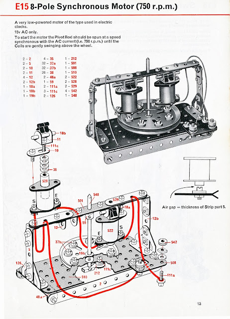
I almost gave up on this one but after spending a few hours talking Stephen Jeavons, at the Runnymede Meccano Guild meeting yesterday, I managed to get the thing going! The secret is getting the adjustment of the coils above the rotor set so the cores are set as near as possible to the thickness of a perforated strip, and getting the rotor to spin at the correct speed.


On Stephen's advice I fitted a 19t pinion to the top of the rotor shaft and that made it much easier to start. 750 RPM, or in other words that is 12½ revolutions per second, is the speed the rotor has to be spun at to get it to synchronise with the AC supply frequency (50 Hz here in the UK). 

The rebuilt E15
I also changed the solenoid hanging brackets (to ensure they were all matched), the insulated strip was changed for a stiffer one and I swapped the original red pulley for a lighter (weight) blue one.   I followed the original instructions as below. The only eventual addition was the 19t pinion to make starting it easier. As with the E12 motor, I had previously built, It would benefit from a few modifications. The coils still don't hang very nicely and the frame could do with beefing up, but it does what it is supposed to do and that makes me happy - for now!

I don't like the way the coils do not hang very nicely
The Elektrikit was intended to be used with a 1960s set No.3 or above. The instructions only use parts available in the No.3 set. Ignoring those limitations would open up all sort's of possibilities for improvement but that was not the point of this exercise. I set out to see if I could get the motor to work within the confines of the parts as listed and, excluding the 19 pinion, I did - Great fun!

The original instructions from the Elektrikit manual

Two down, I wonder which one to tackle next - I should really get on with the Merry Mixer...

...or I could have a go at one of the models from the Electronic Control set. That might make a change...
Electronic control set - Hmmm...

Ralph.

Thursday, 3 October 2013

More Elektrikit - E15 this time!

Elektrikit E15 - Synchronous Motor
Last Saturday I built the Asynchronous motor from the Elektrikit instruction manual (model E15) and it worked surprisingly well. This one is a different matter altogether. The picture above shows the finished model. It may look pretty but I can't get it to work built as the instruction manual shows. I think I might have to give up trying and rebuild it with a few improvements and see what happens. I have started a thread about the build on the Rust Bucket forum HERE.

More soon...

Ralph.

Sunday, 29 September 2013

Wooden Meccano? - No, it's BILOfix!


BILOfix cat

Last week, when we collected the Meccano we have been talking about in recent posts, the seller offered us a collection of BILOfix. Having never heard of it before, I was a bit hesitant. There was a considerable amount of the stuff on offer so we decided to take it and struck a deal. Expecting to return home, do an internet search and discover that we were the only people in the known civilised world who had never heard of it. How wrong can you be. I am amazed how little there is out there regarding this superbly made construction toy. An eBay search revealed nothing - not one piece for sale. A wider internet search relieved a little more information but not a lot other than it was made by Lego. I am working on a separate page over the next week or so where I will detail all I know about the system and invite contributions to help fill in any gaps.

A crane truck - it can slew and hoist
I am not going to say too much here as this stuff is not Meccano but it is interesting and as the picture below illustrates it's huge!

Size comparison; BILOfix and standard Meccano 6-hole strips
I have started a dedicated page for BILOfix HERE so keep an eye on it over the next few weeks and on for the latest news and models.

Ralph.

Saturday, 28 September 2013

20V AC motors and me!


The E020 motor affectionately known at the Cricket-ball motor

We have a motley collection of motors, all sorts from sideplates to modern geared motors and just about everything else between. I would not profess to have all the minor variations but we are not collecting them, we build with them, or at least that is the idea. 

I have always thought of the Meccano motor as being either under powered, noisy or both. For these reasons all our recent, powered models, have utilised modern motors that are much more efficient and advantageously tend to be much smaller.  This week we bought a modest collection of Meccano and amongst it were a couple of 20V motors. One is a  spherical 'cricket-ball' motor and the other is a 20V long sideplate motor. Having never owned a cricket-ball motor before I thought I would give it a test and see if ran. After a bit of maintenance, and some oil in the correct places, it ran very well. This combined with the fact that I found the original pulley, in the box of Meccano that came with it, has made me reconsider using it in a model. looking for ideas I scanned through our collection of manuals and could find nothing, but the robot in the 1947, No.7-8 manual, model number 8.14. The only other reference can find to it (at the time of writing) is in the Gears manuals - both A and B.  The relevant extract is reproduced below. 

That is one way of making it useful...
I am thinking we will have to just build it into a contemporary model of the time or just build one of our own. It seems that Meccano were not overly keen to promote its sale or did the Second World War curtail its promotion.

Rather tatty but a good runner
Along with the cricket-ball motor there was a rather tatty, red, long sideplate motor. This thing has seen a bit of life, but as with the cricket-ball motor it seemed to be a good runner, after a spot of maintenance. As you can see, I need to locate some spares for it. The reversing plate has the top lug snapped off and the terminal nuts and oilers are missing. It looks like another candidate for building into a model. This time I had no trouble finding ideas there are lots of interesting examples in the manuals covering a long period of time - I feel another crane coming on...

Ralph.

Elektrikit Asynchronous Motor

Ekektrikit model E12
Like most of us, my association with Meccano goes back to my youth. Although we never went short of anything, we were not rolling in money and at times I am sure my parents sacrificed a lot to keep food on the table and pay the bills. Money for meccano was practically non-existent so I had to rely on Christmas and birthday presents to increase my stock. There was one thing that I remember always wanting, and I can remember my Father telling me he would love to be able to buy it for me but it was just not possible this year. I know he was genuine as he was obviously keen on the idea himself. The day it was possible for my Father to buy it never came. That illusive set was the Elektrikit.

Years later my father had a stroke and he and my Mother came to stay with us for a while after he had gone through a long hospitalised recovery. He was very keen to do something with his hands as a sort of therapy, so I got out the Elektrikit I had eventually acquired from the late Bert Love some years earlier. We sat in our front room, with bits all over the place, and proceeded to build some of the models we had seen in the advertising decades earlier. Although my Father's dexterity was not too good, between us we built some models. We both had a thoroughly good day and one that I will never forget.

Apart from that day I don't think I have built many (if any) models from that manual until yesterday. A post on Rust Bucket, the Meccano forum, set me off again and it was out with the manual and time to select some parts. The model being discussed on the forum was model number E12, a self starting synchronous motor.

The instructions for the original UK Elektrikit manual
The model itself is straightforward. I built it to the instructions using some parts from the modern sets combined with nice clean, specially selected, Elektrikit parts. The only problem was I didn't have a 15V AC supply to hand, as the instructions recommend. and certainly not a vintage one. The nerest I have is an old Meccano 20V transformer (T20M), so that was pressed into use.

It is always worth checking the resistance of the coils to check they are not faulty. Most of mine are 16Ω (I assume this is what they were meant to be) giving a total  resistance of 32Ω, as the two coils are wired in series. My T20M Transformer gives out about 24V so the current draw in round figures should be about 750 mA (V/R = I ). In fact it will probably be less as I bet there will be some resistance on all those joints!

The finished model with the card removed to show the workings
I have used genuine Elektrikit wire as I wanted to see if it worked built faithfully to the instructions. Although the build is simple, the setting up takes a bit of care. Fine adjustment to the pin-point bearings and to the ends of the strips mounted on the threaded rods really improves the running.

This lower angle shot shows how close the pulley is to the strips

The closer the pulley is to the strips the better only a minimum air gap is required. This obviously necessitates finding 3 inch pulley that runs true. I ended up using one of the dark red pulleys from the vintages set in the end. They are also a bit heaver than the blue ones.


The video shows that the finished motor that self starts and runs like a dream. Towards the end of the video, the sound cuts. This is were I have disconnected the power to the motor and it is continuing  to spin, almost silently, freely in the bearings - great fun. I might just go and have a go at something else from the Elektrikit manual...

Ralph.